
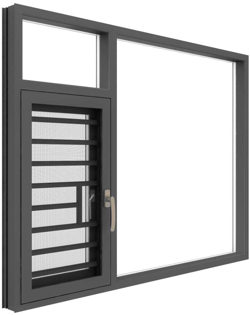
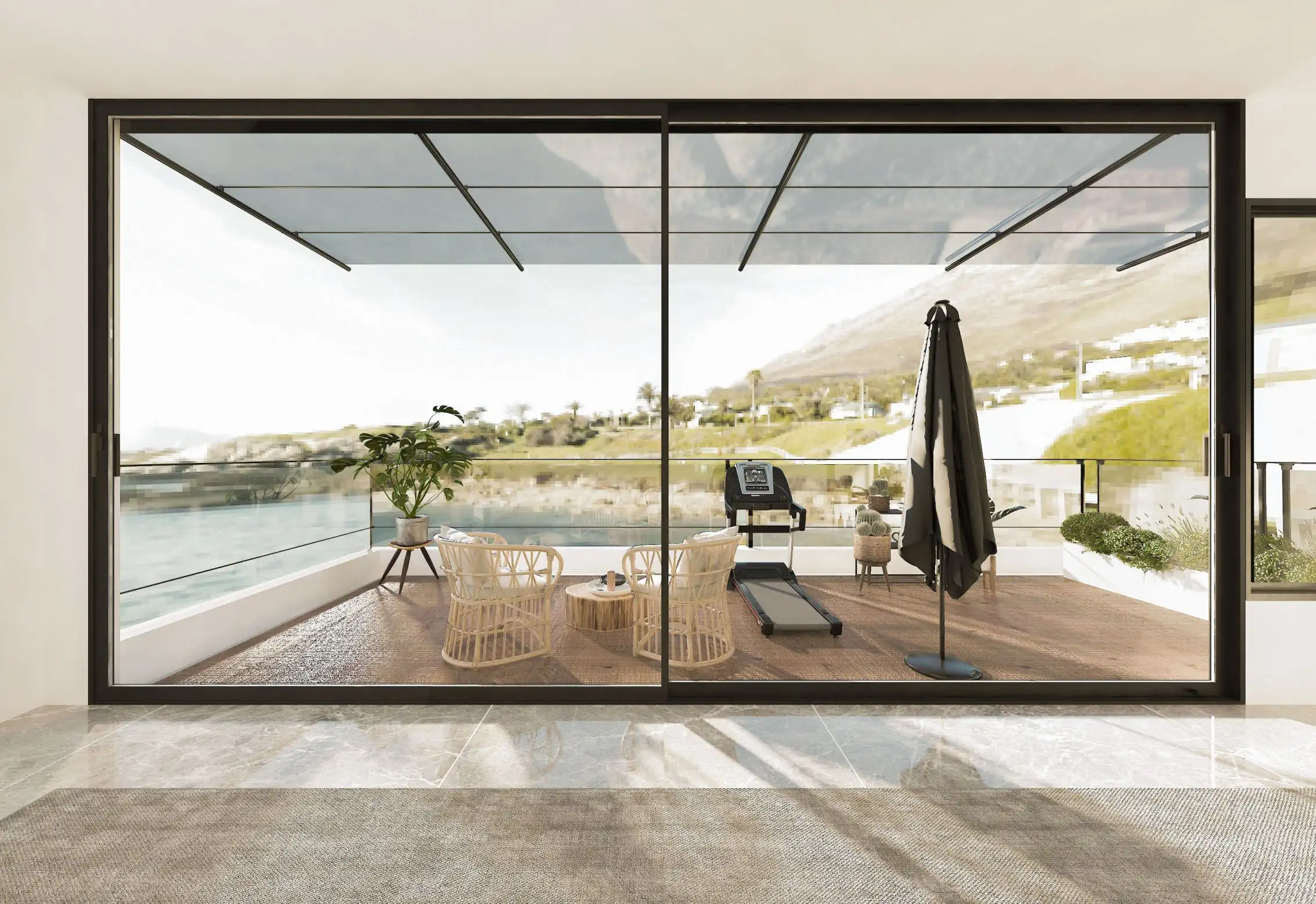
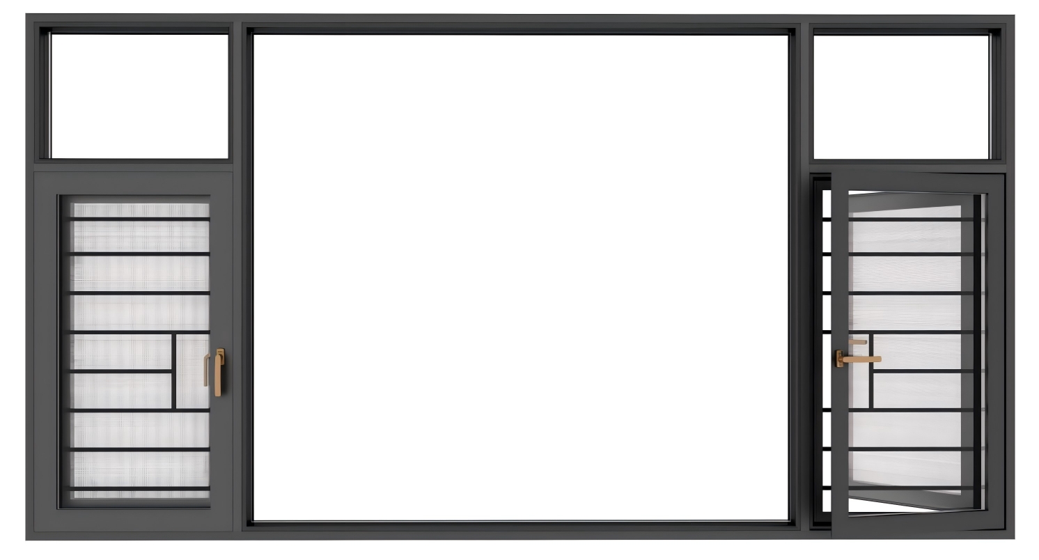
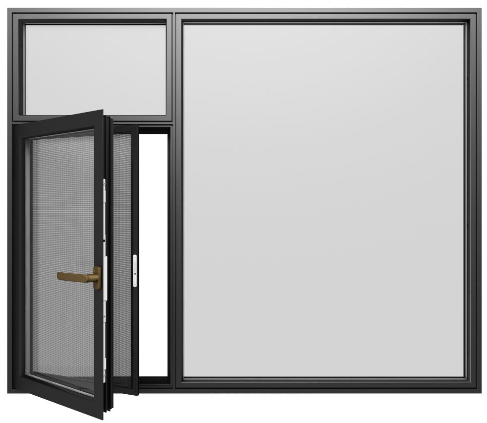
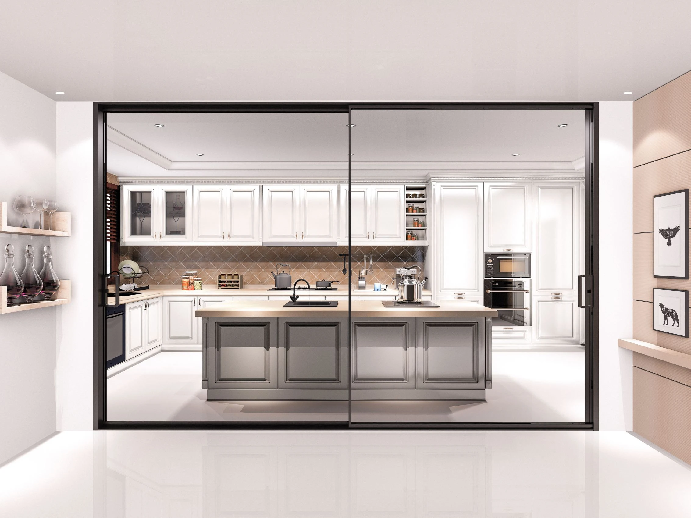
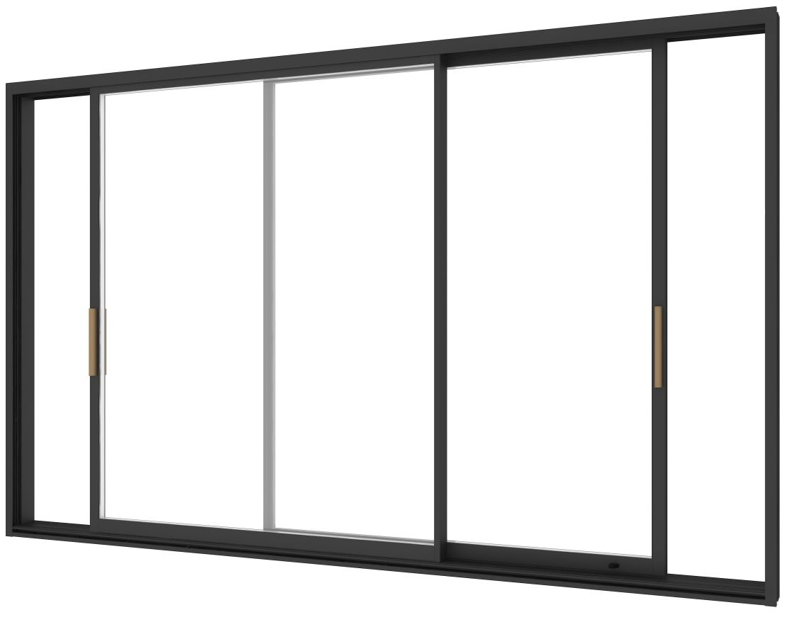
Una guida tecnica completa per gli appaltatori e i gestori di impianti sull'installazione di 150 Porta scorrevole con cornice stretta per esterni Sistemi. L'articolo illustra la preparazione pre-installazione, le procedure di montaggio passo-passo, i requisiti di integrazione strutturale e le tecniche di ottimizzazione delle prestazioni per garantire installazioni a prova di intemperie e conformi alle norme per progetti commerciali e residenziali di alto livello. Il design a cornice stretta massimizza l'area vetrata mantenendo l'integrità strutturale, richiedendo protocolli di installazione precisi per ottenere prestazioni termiche ottimali e longevità operativa in ambienti esterni esposti.
Requisiti pre-installazione e preparazione del sito
Valutazione strutturale e specifiche di apertura
Prima di iniziare l'installazione, effettuare una valutazione strutturale completa del sito di installazione. La capacità di carico deve soddisfare il peso operativo del sistema e i carichi dinamici del vento. Per le configurazioni standard 150 Outdoors, verificare la capacità del substrato per un carico distribuito minimo di 150 kg/m².
Tolleranze di apertura grezza: Mantenere la precisione dimensionale entro ±3 mm sia per le misure di larghezza che di altezza. Le aperture di larghezza superiore a 3 m richiedono montanti di supporto intermedi progettati secondo lo standard ISO 12567-1 per i ponti termici. Misurare le dimensioni diagonali per confermare l'ortogonalità; differenze superiori a 5 mm richiedono correzioni di spessoramento prima dell'installazione del telaio.
Requisiti di compatibilità del substrato:
- Calcestruzzo/muratura: Spessore minimo di 150 mm, polimerizzazione di 28+ giorni, planarità della superficie ±2 mm su una campata di 2 m.
- Cornici in acciaio: Canali a C zincati a caldo, spessore minimo di 2,5 mm, collegamenti saldati agli angoli.
- Cornice in legno: Legname ingegnerizzato (LVL/Glulam) classificato per esposizione esterna, contenuto di umidità <15%, trattato secondo gli standard AWPA U1.
Verificare i punti di integrazione della scossalina perimetrale. Il profilo stretto della lunetta richiede precisi giri di scossalina, con sovrapposizioni minime di 100 mm agli angoli e piani di drenaggio continui dietro il telaio. Documentare le condizioni della membrana impermeabile esistente; materiali incompatibili (ad esempio, membrane a base di asfalto o sintetiche) richiedono strati di isolamento.
Lista di controllo degli strumenti, dei materiali e delle attrezzature di sicurezza
Toolkit essenziale per l'installazione:
- Strumenti di precisione: Livella laser digitale (precisione ±0,5 mm/m), chiavi dinamometriche a quadrante (gamma 0-25 Nm), calibri digitali per la verifica della compressione della guarnizione.
- Utensili elettrici: Trapano a percussione rotante con punte in carburo per muratura (Ø10-16 mm), avvitatore a percussione a batteria con comando a frizione, pistola pneumatica per sigillanti per composti ASTM C920
- Strumenti manuali: Barre di alluminio (antitraccia), mazzette di gomma (500 g), spessori in acciaio inox (incrementi da 0,5 a 5 mm).
Specifiche dei dispositivi di fissaggio per ambiente:
- Zone costiere (<5 km da acqua salata): Ancoraggi in acciaio inossidabile di grado 316, diametro minimo 12 mm, profondità di inserimento 80 mm nel calcestruzzo.
- Ambienti standard: Acciaio inossidabile di grado 304 o zincato a caldo, diametro 10 mm, incasso 65 mm.
- Regioni con vento forte (velocità del vento di progetto >140 km/h): Sistemi di ancoraggio ingegnerizzati con certificati di prova di carico, distanziati a intervalli massimi di 400 mm.
Attrezzature di sicurezza secondo OSHA 1926 sottoparte E:
- Imbracature anticaduta per installazioni superiori a 1,8 m
- Occhiali di sicurezza con schermi laterali (ANSI Z87.1)
- Guanti antitaglio (minimo ANSI A4) per la manipolazione dei pannelli.
- Protezione delle vie respiratorie durante l'applicazione del sigillante in spazi chiusi
Procurarsi sigillanti adatti alle condizioni atmosferiche: Silicone ASTM C920 Classe 25 con capacità di movimento di ±25%, compatibile con substrati di alluminio e vetro. Verificare le tabelle di compatibilità del produttore: primer incompatibili possono compromettere l'adesione in applicazioni con cornici strette, dove i giunti del sigillante sono visivamente evidenti.
Processo di installazione passo dopo passo
Sequenza di montaggio e ancoraggio del telaio
Protocollo di installazione del binario inferiore:
Iniziare con la traccia del davanzale, in quanto stabilisce la geometria di base del sistema. Applicare un letto continuo di sigillante poliuretanico (cordolo di 6 mm) lungo la superficie di contatto con il substrato. Posizionare il binario con morsetti temporanei, quindi verificare la planarità sull'intera campata, con una deviazione massima di 1 mm per 3 m di lunghezza. Nelle configurazioni a più pannelli di lunghezza superiore a 6 m, introdurre spessori intermedi di livellamento a intervalli di 1,2 m.
Procedura di perforazione dell'ancora:
- Segnare le posizioni di ancoraggio a 450 mm di distanza, sfalsate di 75 mm dalle estremità dei binari.
- Eseguire i fori pilota alla profondità specificata più 15 mm per la distanza dai detriti.
- Pulire i fori con l'aria compressa o l'aspirazione a vuoto
- Installare gli ancoraggi a tenuta di dita, quindi serrare a 18-22 Nm con uno schema centrale verso l'esterno.
Allineamento dello stipite verticale:
Montare gli stipiti laterali utilizzando controventature provvisorie ad angoli di 45°. Controllare la messa a piombo con una livella di 2 metri, con una tolleranza di ±1 mm per metro di altezza. Il design stretto della cornice amplifica le irregolarità visive; le deviazioni oltre le specifiche creano interruzioni evidenti della linea visiva. Fissare gli stipiti con bulloni di ancoraggio a una distanza verticale di 600 mm, mantenendo una distanza di 25 mm dal perimetro del telaio.
Installazione del binario della testa:
Posizionare il binario di testa con spazi di dilatazione di 5 mm in corrispondenza di ogni giunzione dello stipite, fondamentale per il movimento termico in applicazioni esterne in cui i componenti in alluminio subiscono oscillazioni di temperatura di ±15°C al giorno. Il profilo stretto del sistema 150 concentra le sollecitazioni termiche; un margine di dilatazione insufficiente provoca l'incollaggio del telaio o l'estrusione della guarnizione. Verificate le misure diagonali dopo l'assemblaggio: differenze superiori a 3 mm indicano la presenza di crepe che devono essere corrette prima di procedere.
Montaggio dei pannelli e integrazione dell'hardware
Montaggio del carrello a rulli:
Fissare i carrelli a rulli alle guide superiori del pannello utilizzando bulloni in acciaio inox M8. Applicare un frenafiletti (mediamente resistente) e serrare a 10 Nm ±1 Nm, specifica critica per il sistema di cornici strette, dove un serraggio eccessivo deforma i sottili profili in alluminio. Posizionare i carrelli a 150 mm dai bordi del pannello per una distribuzione equilibrata del carico.
Sequenza di installazione del pannello:
- Sollevare i pannelli con un angolo di 15° per agganciare i rulli con i canali del binario della testa.
- Perno dei pannelli in verticale con sostegno del bordo inferiore
- Guidare la guida inferiore nel binario del davanzale, assicurandosi che la guarnizione di tenuta si inserisca nel substrato.
- Regolare l'altezza del rullo con le viti di regolazione integrate.
Calibrazione della compressione delle guarnizioni:
Il design stretto della cornice si basa su una precisa compressione delle guarnizioni per garantire la resistenza alle intemperie. Utilizzando uno spessimetro, verificare la compressione di 30-40% delle guarnizioni perimetrali quando i pannelli sono chiusi. Una compressione insufficiente (50%) aumenta la forza operativa e accelera il degrado della guarnizione. Regolare l'altezza dei pannelli con incrementi di 0,5 mm per ottenere le specifiche.
Allineamento del meccanismo di blocco:
Installare le serrature multipunto con le piastre di riscontro posizionate per una profondità di innesto di 3-5 mm. Testate il funzionamento della serratura per 10 cicli completi: l'innesto senza impedimenti conferma il corretto allineamento. La profondità minima del telaio della cornice stretta richiede un posizionamento preciso delle piastre di riscontro; un disallineamento di 2 mm può impedire l'innesto completo, compromettendo la sicurezza e la tenuta agli agenti atmosferici.
Protocollo di sigillatura e protezione dagli agenti atmosferici
Applicazione del sigillante perimetrale:
Applicare il silicone ASTM C920 Classe 25 in un cordone continuo lungo tutti i giunti tra telaio e substrato. Mantenere una larghezza del cordone di 6 mm × una profondità di 8 mm per un adattamento ottimale al movimento. Utilizzare il sigillante entro 5 minuti dall'applicazione per garantire una corretta adesione e la formazione di un profilo concavo, fondamentale per l'estetica della cornice stretta, dove le linee del sigillante sono visivamente evidenti.
Standard di configurazione comune:
- Giunti tra telaio e stipite: 10 mm di larghezza, barra di rinforzo a 12 mm di profondità
- Giunti di raccordo tra il materiale e il substrato: Larghezza 12 mm, supporto in schiuma a cellule chiuse
- Giunti di dilatazione per binari di testa: larghezza 8 mm, nastro adesivo sulla superficie centrale
Posizionamento del foro di sfiato:
Installare coperture per i fori di drenaggio a intervalli di 800 mm lungo il tracciato del davanzale. Posizionare le uscite a 5 mm sopra la quota esterna per evitare il riflusso in caso di forti precipitazioni. La ridotta profondità del telaio del sistema a cornice stretta limita la capacità di drenaggio interno; i fori di drenaggio correttamente posizionati impediscono l'accumulo di acqua che potrebbe compromettere il taglio termico.
Verifica della continuità del taglio termico:
Ispezionare le interruzioni termiche in poliammide su tutti i giunti del telaio utilizzando la termografia (se disponibile) o la conferma visiva di strisce isolanti continue. Gli spazi vuoti superiori a 2 mm nei giunti termici annullano le prestazioni energetiche del sistema, in particolare nel caso di cornici strette, dove la massa ridotta del telaio accelera il trasferimento termico.
Test delle prestazioni e verifica della conformità
Procedure di test operativo
Protocollo di prova della forza secondo ANSI A156.10:
Misurare la forza di apertura della porta utilizzando una bilancia a molla calibrata fissata alla posizione della maniglia di trazione. Applicare la forza perpendicolarmente al piano della porta e registrare la forza di trazione massima. Le specifiche richiedono <50N (11,2 lbf) per l'accessibilità conforme al codice. I carrelli a rulli di precisione del sistema a cornice stretta raggiungono in genere 30-40N quando sono regolati correttamente; il superamento di questo intervallo indica un disallineamento o la presenza di detriti nei binari.
Test di infiltrazione dell'aria secondo AAMA 501:
Eseguire il test della porta soffiante con una pressione differenziale di 75 Pa (equivalente a un vento di 30 km/h). Tassi di infiltrazione accettabili per il sistema 150 Outdoors: <0,3 L/s/m² di area del telaio. Utilizzare il fumo teatrale o la termografia a infrarossi per identificare i percorsi delle perdite intorno alle guarnizioni perimetrali. I punti di rottura più comuni nelle installazioni con cornici strette sono gli angoli e i giunti di dilatazione dei binari di testa.
Test di penetrazione dell'acqua:
Applicare un getto d'acqua calibrato (3,4 L/min/m²) mantenendo 20% della pressione del vento di progetto. Monitorare le superfici interne per verificare l'intrusione di acqua per una durata di 15 minuti. La ridotta profondità della soglia richiede una maggiore capacità di drenaggio: verificate che i fori di drenaggio scarichino liberamente durante il ciclo di prova.
Calibrazione del sensore di sicurezza:
Per i sistemi automatizzati, testare i sensori di ostruzione utilizzando un oggetto di prova di 50 mm di diametro posizionato nel percorso della porta. Verificare l'inversione della porta entro 50 mm dal contatto secondo gli standard UL 325. Regolare la sensibilità del sensore per evitare falsi inneschi dovuti a detriti trasportati dal vento, pur mantenendo un rilevamento affidabile delle ostruzioni.
Conformità al codice e documentazione
Requisiti IBC per le uscite di sicurezza:
Verificare che la larghezza dell'apertura libera soddisfi il valore minimo di 32″ (815 mm) secondo la norma IBC 1010.1.1. Misurare con la porta in posizione completamente aperta, tenendo conto della ferramenta sporgente. Il design della cornice stretta massimizza l'apertura libera rispetto alle dimensioni del telaio: una porta di 1200 mm offre in genere una larghezza libera di 1140 mm, superando i minimi del codice di 28%.
Conformità all'accessibilità ADA:
Documentate le seguenti misure per la certificazione dell'accessibilità:
- Altezza della soglia: Massimo 13 mm (½")
- Forza di apertura: <50N come verificato nei test operativi
- Spazio di manovra: 1525 mm di profondità sul lato di trazione, 1220 mm sul lato di spinta
- Altezza di montaggio della ferramenta: 865-1220 mm dal pavimento finito
Presentazione della certificazione del carico del vento:
Preparare un pacchetto di documentazione ingegneristica che comprenda:
- Calcoli strutturali secondo le disposizioni ASCE 7 sul carico del vento
- Risultati delle prove di trazione degli ancoraggi (fattore di sicurezza minimo 3:1)
- Schede tecniche del vetro che confermano i valori di pressione di progetto
- Sigillo di un ingegnere professionista che certifica la conformità al codice
Presentare la documentazione alle autorità edilizie locali almeno 48 ore prima dell'ispezione finale. Il design innovativo del sistema a cornice stretta può richiedere una revisione ingegneristica aggiuntiva nelle giurisdizioni che non conoscono il prodotto.
Matrice delle specifiche di installazione
| Parametro di installazione | Specifiche standard | Intervallo di tolleranza | Standard di test |
|---|---|---|---|
| Profondità del telaio | 150 mm | ±1,5 mm | ISO 12567-1 |
| Peso del pannello (per m²) | 45-65 kg | ±5% | ASTM E2068 |
| Campata massima singola | 3000 mm | -0/+10 mm | AAMA 501.4 |
| Distanza tra gli ancoraggi (perimetro) | Centri da 450 mm | ±25 mm | ACI 318 |
| Coppia di ancoraggio (calcestruzzo) | 20 Nm | ±2 Nm | Specifiche del produttore |
| Larghezza del giunto sigillante | 6-12 mm | ±1 mm | ASTM C920 |
| Gamma di regolazione del rullo | ±8 mm verticale | Incrementi di 0,5 mm | ANSI A156.10 |
| Continuità del taglio termico | Contatto 100% | 0% lacune >2mm | ISO 10077-2 |
| Tasso di infiltrazione dell'aria | <0,3 L/s/m² | @75 Pa pressione di prova | AAMA 501.1 |
| Resistenza alla penetrazione dell'acqua | Nessuna infiltrazione | Pressione di progetto @20% | ASTM E1105 |
| Forza operativa | <50N | ±5N | ANSI A156.10 |
| Larghezza di apertura libera | 95% della larghezza della porta | -0/+5 mm | IBC 1010.1.1 |
Risoluzione dei problemi più comuni dell'installazione
Allineamento e problemi operativi
Sintomi e correzioni del trascinamento del pannello:
Se i pannelli presentano una maggiore resistenza al rotolamento o rumori di raschiamento, effettuare un controllo sistematico:
- Regolazione dell'altezza del rullo: Ruotare le viti di regolazione in senso orario con incrementi di 0,5 mm finché il trascinamento non cessa. Le strette tolleranze della lunetta richiedono regolazioni graduali: una correzione eccessiva crea un contatto opposto.
- Accumulo di detriti sui binari: Rimuovere i pannelli e aspirare i binari con gli strumenti interstiziali. La polvere di costruzione nei canali stretti dei binari crea punti di attrito invisibili durante l'ispezione visiva.
- Scaffalatura a telaio: Verificare nuovamente le misure diagonali. Un'inclinazione superiore a 3 mm fa deviare i binari fuori dal loro parallelo, causando un progressivo inceppamento durante l'attraversamento dell'apertura da parte dei pannelli.
Protocollo di eliminazione delle perdite d'aria:
Identificare i punti di perdita utilizzando il fumo d'incenso o le immagini termiche in condizioni di vento. Punti di guasto comuni nelle installazioni con cornici strette:
- Angoli di raccordo: Iniettare ulteriore sigillante con applicatori a punta d'ago, assicurando il completo riempimento dei vuoti.
- Giunti di dilatazione: Sostituire il tondino di supporto deteriorato e risigillare con un composto ASTM C920 fresco.
- Guarnizioni di tenuta: Regolare la compressione del pannello o sostituire le guarnizioni usurate: una compressione inferiore a 25% indica un guasto alla guarnizione.
Gestione del gap di espansione termica:
Le variazioni di temperatura stagionali causano un movimento di ±5 mm in campate di alluminio di 3 metri. Si creano fessure di dilatazione insufficienti:
- Estate: Inclinazione del telaio, funzionamento difficoltoso, estrusione della guarnizione
- Inverno: Apertura della fessura, aumento dell'infiltrazione, condensazione
Verificare distanze minime di 5 mm in tutti i giunti di dilatazione. In climi estremi (sbalzi di temperatura >40°C), aumentare le distanze a 8 mm e utilizzare sigillanti a movimento più elevato (capacità di ±35%).
Attenuazione della condensa:
La condensa interna sui telai stretti della cornice indica un guasto del taglio termico o una ventilazione inadeguata. Verificare:
- Contatto continuo a taglio termico su tutti i giunti del telaio
- Livelli di umidità interna <50% RH durante la stagione di riscaldamento
- Adeguata circolazione dell'aria sulle superfici vetrate (velocità minima dell'aria di 0,5 m/s)
Modulo FAQ
Q1: Qual è la tolleranza minima di apertura grezza richiesta per i sistemi 150 Outdoors Narrow Bezel?
Mantenere le dimensioni grezze dell'apertura entro ±3 mm dalle dimensioni del telaio specificate, sia in larghezza che in altezza. La profondità minima del telaio (150 mm) del design a cornice stretta offre un margine di regolazione inferiore a quello dei sistemi tradizionali; aperture superiori alla tolleranza richiedono correzioni di spessoramento che possono compromettere le prestazioni termiche. Verificare l'ortogonalità misurando le diagonali; differenze superiori a 5 mm richiedono correzioni strutturali prima dell'installazione del telaio.
D2: Come posso verificare la corretta resistenza alle intemperie dopo l'installazione in ambienti costieri?
Eseguire le prove di spruzzatura d'acqua AAMA 501 a 20% della pressione del vento di progetto per almeno 15 minuti. Le installazioni costiere richiedono prove più approfondite: aumentare la velocità di spruzzo a 5 L/min/m² e prolungare la durata a 30 minuti per simulare le condizioni di tempesta. Verificare che i fori di drenaggio scarichino liberamente per tutta la durata del test. Utilizzare elementi di fissaggio in acciaio inossidabile di grado 316 e applicare una protezione anticorrosione aggiuntiva (primer ricco di zinco) ai punti di ancoraggio esposti. Programmare ispezioni annuali per monitorare le condizioni del sigillante: l'esposizione ai raggi UV della costa e la nebbia salina ne accelerano il degrado.
D3: Quali sono le specifiche di coppia richieste per l'ancoraggio del binario inferiore in substrati di cemento?
Serrare gli ancoraggi perimetrali a 20 Nm ±2 Nm utilizzando una chiave dinamometrica calibrata. Applicare la coppia di serraggio con uno schema centro-esterno per evitare la distorsione del telaio. Per installazioni costiere o con vento forte, aumentare a 22 Nm e ridurre la distanza tra gli ancoraggi a 400 mm. Prima dell'installazione, verificare che la resistenza del substrato di calcestruzzo sia superiore a 20 MPa; una resistenza inferiore richiede ancoraggi di diametro maggiore (12 mm contro 10 mm) o ancoraggi con fissaggio epossidico per garantire un'adeguata resistenza allo strappo. Un serraggio eccessivo oltre i 24 Nm rischia di spanare le filettature dei profili in alluminio della cornice stretta.
Il successo dell'installazione dei sistemi per porte scorrevoli 150 Outdoors Narrow Bezel richiede una preparazione strutturale precisa, il rispetto delle specifiche di coppia e di allineamento del produttore e protocolli rigorosi di protezione dagli agenti atmosferici. I vantaggi estetici del design a cornice stretta - massimizzazione dell'area vetrata e minimo ingombro visivo - richiedono una maggiore precisione di installazione rispetto ai sistemi tradizionali. I fattori critici di successo includono il mantenimento di tolleranze di apertura grezze di ±3 mm, il raggiungimento della compressione delle guarnizioni 30-40% e la garanzia di un'integrità continua del taglio termico in tutti i giunti del telaio.
Una corretta installazione offre vantaggi prestazionali a lungo termine: tassi di infiltrazione d'aria inferiori a 0,3 L/s/m², forze operative inferiori a 40N per la conformità all'accessibilità e una durata di progetto superiore a 25 anni in ambienti esterni difficili. La conformità ai requisiti IBC per le vie di fuga, agli standard di accessibilità ADA e alle disposizioni ASCE 7 per il carico del vento protegge sia la responsabilità dell'installatore che l'investimento del proprietario dell'edificio.
Per un supporto tecnico specifico per il progetto, compresi i calcoli della portata, la verifica della compatibilità del substrato o le specifiche dell'ambiente costiero, consultare i partner di installazione certificati o contattare il team di ingegneri del produttore. Un'installazione corretta garantisce la soddisfazione del cliente grazie a decenni di funzionamento affidabile in applicazioni architettoniche ad alta visibilità.